
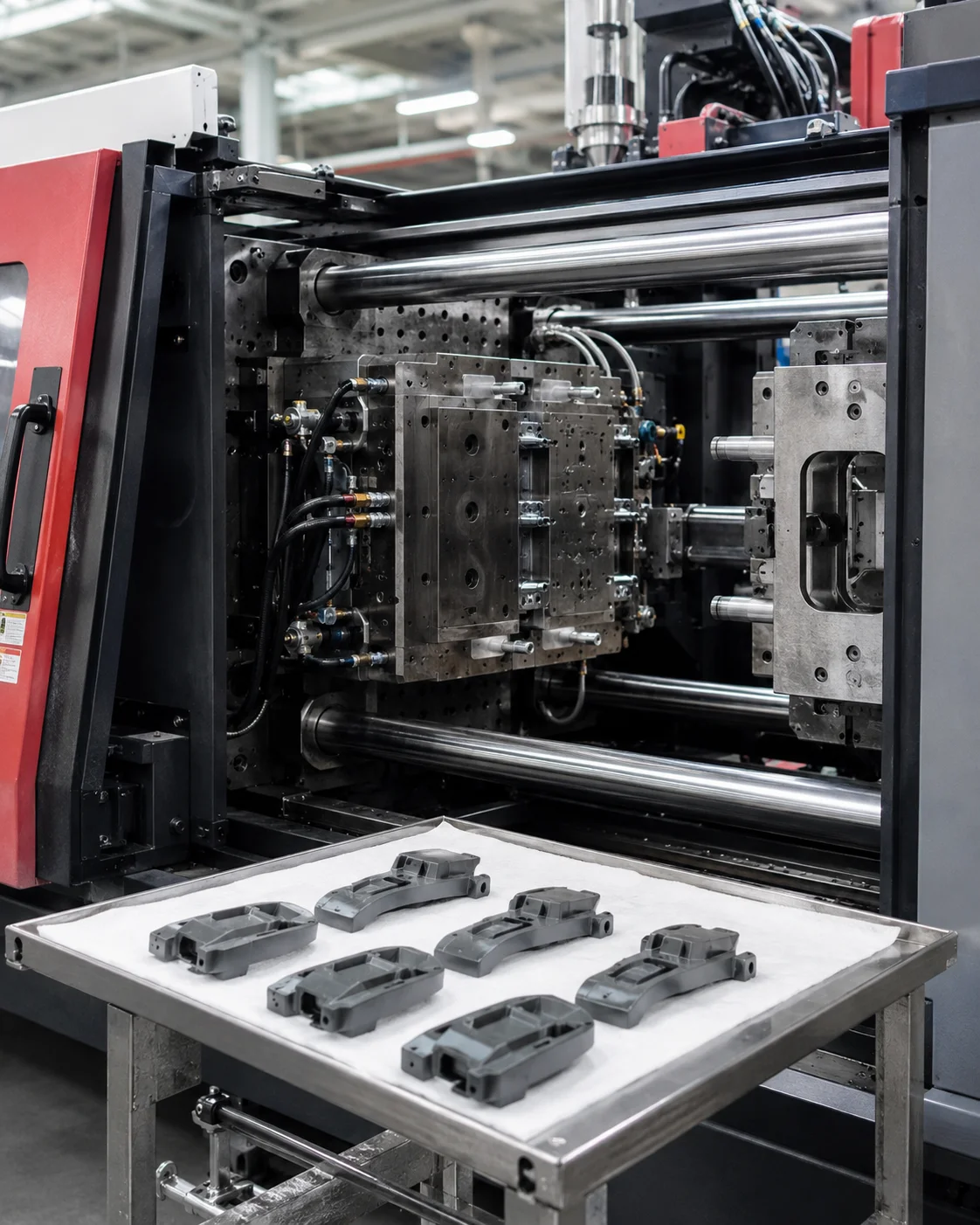
Indirect rapid tooling offers a practical route for producing complex prototypes when a direct tooling approach may not provide the required flexibility. At the center of this process is the master pattern. Its dimensional accuracy, surface finish, geometry, and ability to reproduce fine details can directly influence the quality of the tooling created from it.
For engineering teams developing functional prototypes or preparing for low volume production, understanding the relationship between master pattern quality and final part performance is essential. A high quality master pattern provides a reliable reference for subsequent tooling stages, while inaccuracies introduced at the beginning can affect every stage that follows.
Why the Master Pattern Matters in Indirect Rapid Tooling
Indirect rapid tooling introduces an additional manufacturing stage between the original design and the final mold. Instead of machining the final tooling directly from the CAD model, a master pattern is first produced and then used to create the subsequent tooling.
This means the master pattern becomes an important physical representation of the intended geometry. If its dimensions, contours, or surface characteristics are inaccurate, those differences can be transferred into the tooling and eventually appear in molded parts.
The principle is straightforward: the quality of the master pattern establishes the reference for the next stage. That makes early dimensional verification particularly important for projects involving tight tolerances, complex surfaces, or highly visible cosmetic features.
Dimensional Accuracy Controls the Final Geometry
Dimensional accuracy is one of the most important factors when evaluating a master pattern for indirect rapid tooling. Even a small deviation in a critical feature can affect the dimensions of the resulting tool and molded component.
This becomes more significant when the prototype includes mating surfaces, mounting points, sealing interfaces, holes, or other features that must align with existing components. If the master pattern does not accurately represent the approved CAD geometry, correcting the problem later can require additional tooling modification.
HordRT incorporates dimensional control throughout its tooling workflow. Its rapid tooling process includes engineering review, DFM analysis, tool manufacturing, component inspection, mold assembly, trial molding, and final validation. Critical mold dimensions are inspected during machining and before assembly, while T1 samples are evaluated for dimensions, appearance, and functional performance.
This staged approach helps separate design variation from tooling and molding variation before a project moves forward.
Surface Finish Starts With the Pattern
Surface finish is another area where master pattern quality can have a direct effect on the final result. A polished surface, fine texture, matte appearance, or cosmetic contour must be accurately represented and transferred through the tooling process.
If the master pattern contains unwanted machining marks, scratches, inconsistent polishing, or incomplete texture definition, those characteristics may influence the resulting mold surface. For appearance sensitive products, this can create additional finishing work or require changes to the tooling process.
HordRT evaluates surface requirements during DFM and mold design. Its tooling capabilities include polishing, bead blasting, EDM texture, fine texture, matte finishes, high gloss surfaces, and other application specific requirements.
For projects with demanding cosmetic specifications, defining the required finish before manufacturing allows the master pattern, tooling surface, and final molded part to be evaluated as one connected process.
Detail Reproduction Requires a Precise Reference
Small features often create the biggest challenges in prototype tooling. Fine ribs, narrow grooves, lettering, logos, textured areas, deep cavities, and complex transitions require accurate reproduction at every stage.
The master pattern therefore needs to preserve these details without unnecessary distortion. This is particularly important for complex prototype geometries where the visual appearance and functional behavior depend on small design features.
HordRT combines CNC machining with EDM, wire cutting, precision finishing, fitting, and inspection to manufacture tooling components. Its engineering workflow also considers part geometry, inserts, undercuts, slides, lifters, and other tooling mechanisms during design.
Such capabilities are useful when the indirect tooling process involves transferring intricate features rather than reproducing a relatively simple cavity.
Shrinkage Must Be Considered Before the Tool Is Made
Dimensional accuracy is not determined by the master pattern alone. Material behavior also matters. Injection molding materials can experience shrinkage during cooling, and different resins may produce different dimensional results.
For this reason, material selection and expected shrinkage should be considered before tooling is manufactured. A master pattern that is dimensionally correct according to CAD does not automatically mean the molded part will have identical dimensions after processing.
HordRT reviews resin, volume, tolerance, mold life, and part requirements during its project review. Its rapid tooling process also includes mold trials and sample inspection, providing an opportunity to evaluate the actual molding result rather than relying only on theoretical dimensions.
This is especially valuable for prototype programs where the goal is functional validation rather than simply producing a visual model.
Quality Control Should Continue Beyond the Master Pattern
A precise master pattern is important, but it is only one part of an effective indirect rapid tooling workflow. Tool manufacturing accuracy, assembly precision, molding parameters, and inspection all influence the final result.
HordRT uses dimensional inspection, CMM measurement, 3D blue light scanning, and T1 sample validation according to project requirements. Blue light scanning can compare complex molded surfaces against CAD data, helping identify deviations across contours and other difficult surfaces.
HordRT also maintains its own tooling and molding workflow, covering mold design, CNC machining, EDM, wire cutting, fitting, assembly, trial molding, and inspection. This integrated structure gives engineering teams a clearer connection between the original design, tooling development, and final molded parts.
Make the Master Pattern a Reliable Starting Point
Indirect rapid tooling can provide flexibility for complex prototype development, but its effectiveness depends on controlling accuracy from the earliest stage. Dimensional deviations, poor surface preparation, incomplete detail reproduction, and insufficient consideration of material shrinkage can all affect the final tooling and molded parts.
A reliable master pattern gives the subsequent process a stable physical reference. Combined with DFM analysis, controlled tooling manufacturing, trial molding, and dimensional inspection, it can support a more predictable path from prototype design to functional validation.
For projects where geometry, appearance, and dimensional performance all matter, HordRT brings rapid tooling, injection molding, precision machining, engineering review, and quality inspection into one coordinated workflow. Its experience with complex tooling structures and production grade molding materials allows the tooling strategy to be evaluated around the actual requirements of the part rather than treated as a standard prototype process.
When the master pattern is treated as more than an intermediate step and instead as a critical quality reference, indirect rapid tooling becomes easier to control from design intent through final part validation.